New Title
New Paragraph
New Paragraph
New Paragraph
New Title
Follow us
Vehicle Support Platform
The support platform provides a smooth surface in the vehicle for transporting the telescope to a viewing site.


The vehicle support platform provides a place to carry the telescope without damaging the vehicle upholstery. It also provides a place to store the 3/4" plywood ramp that lets you move the cart into the vehicle when you need it to set up the telescope at your observing site.
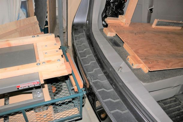
The boards on the left at both ends of the support platform support the 2' x 6' 3/4" plywood ramp used to move the cart into the vehicle for use at the observing site. The ramp and supports are rubber coated to prevent damaging the upholstery, and to prevent vibration when driving the vehicle. Un-padded boards on the sides that face the middle of the platform guide the hinged support platform as the telescope is rolled into the vehicle.
The boards on the left at both ends of the support platform support the 2' x 6' 3/4" plywood ramp used to move the cart into the vehicle for use at the observing site. The ramp and supports are rubber coated to prevent damaging the upholstery, and to prevent vibration when driving the vehicle. Un-padded boards on the sides that face the middle of the platform guide the hinged support platform as the telescope is rolled into the vehicle.
Support the rear edge of the platform so the top is 1/2" or more above the bottom edge of the rear hatch, so the connector board won't damage your upholstery or bumper. The padded front brace (at the top of the left picture) fits between the support platform forks, and keeps the telescope from rolling forward when you brake.
The padded rear brace (picture below) sticks down into the left seat handle socket to prevent the platform from shifting forward or back as you drive. I used rubber gasket material on the front edge so it would fit in the socket. (The rubber pad used elsewhere on this brace was too thick.)

The brace in the back(picture below) is placed over the end of the telescope support platform to keep the tele from scratching the rear hatch when you accelerate. It has 2 2x3s screwed together to fill the gap between the support platform and the rear hatch, and has rubber glued on both sides. The crosswise 1x2 has rubber on the bottom and rests on top of the end of the tele support platform to keep the brace in place. By trial and error, adjust the brace so there is only about 1/4" between the brace and the rear hatch.

The video below shows how to build a ramp to move the cart into the Odyssey, and how to modify the vehicle support platform to store the ramp.
I tried using 2 wooden ramps, built from 2x6s with purchased ramp hardware, instead of the single plywood ramp described in the video. That was more complicated than the single plywood ramp, and the ramps were harder to store in the vehicle, so I don't recommend those. You could use 2 motorcycle ramps, side by side, but most of them cost $70 each, and have to be modified for the small garden cart wheels.
The steps to load the cart through the right door and then store the ramp are slightly different.
Place the ramp in the right door.
Push the cart backwards until it is in the vehicle, store the ramp, push the cart until the rubber bumper is against the ramp. Chock the cart wheels, or brace the cart. Store the tripod under the ramp through the left door, with the legs toward the rear of the vehicle. You may need to move the front seats forward before loading the cart, and you may need to lift each end of the cart to adjust its position as you load it into your vehicle.
Connector board.


Note: all parts on the connector board should be attached with countersunk wood screws from the bottom, so the screws won't interfere with other parts of the system.
(left picture) The connector board joins the extension of the lift table frame with the vehicle support platform for transferring the tele to and from the vehicle. It is 19" wide and 23" long. I recommend making it 22" wide, and make sure the end of the vehicle support platform is high enough to keep the connector from damaging the hatch lip.
(left picture) Screw a 6 inch alignment 1x2 in the middle of the connector perpendicular to the end that connects to the lift table extension, and projects 2 inches past the end toward the cart. (That's a change from what the picture shows.)
(middle picture) Place the connector on the projecting 2x4ss, pressed against the end of the extension and centered left to right. Mount 2 5" 1x2's pressed against the sides of the alignment 1x2. Use #10-24 machine screws so the boards can be adjusted later, if necessary. These 5" 1x2s should project 1" past the end of the extension.
(left picture) With the connector pressed against the extension and aligned, screw the 1x2 guides to each side of the board. The outside edges of the 1x2 guides must exactly match the outer edges of the 2x2s, and the ends of the guides that will connect to the vehicle should be 2" closer together to guide the tele support platform as it rolls from the vehicle to the cart.
(right picture) Cut two 1" 2x4s and bolt them to the 1x2s at the end of the vehicle support platform, so they are 3/8" below the top of the platform. Support them on the bottom with rubber and boards as necessary.